
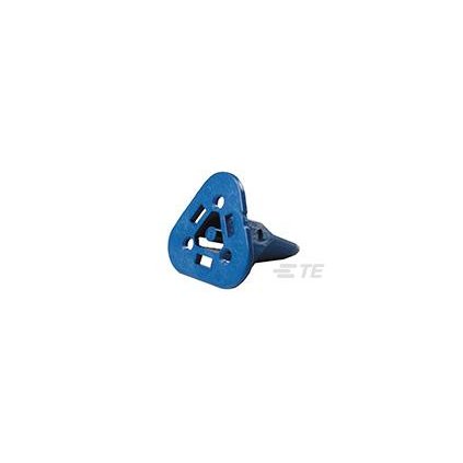
Pojistka kontaktů pro konektory řady Deutsch DT DEUTSCH Sekundární aretace pro CAN - SAE J1939, modrá; počet kontaktů: 3.
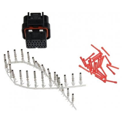
Sada 26 pól.konektoru pro displeje OPUS, Bodas (konektor, 26x S&F dutinka, 26x záslepka)
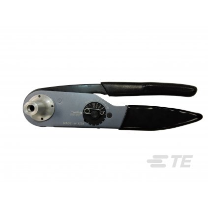
Lisovací kleště pro sypané kontakty IPD #20-#12
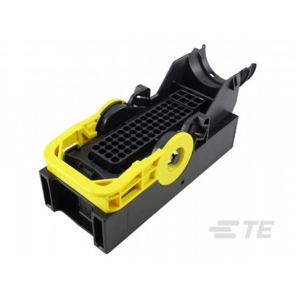
Tělo těsněného kabelového konektoru řady LEAVYSEAL AMP Plug 62 Way AMP MCP 1.5/2.8MM soc; LEAVYSEAL; Black; key A; počet kontaktů: 62
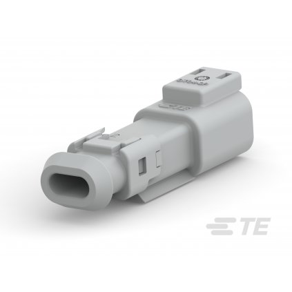
Tělo vodotěsného konektoru řady DT Konektor pro 2x kolík; šedý; e-seal; SnapAdapter
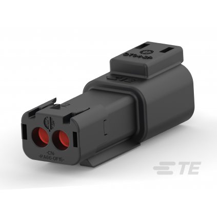
Tělo vodotěsného konektoru řady DT Konektor pro 2x kolík; černý; e-seal; SnapCap
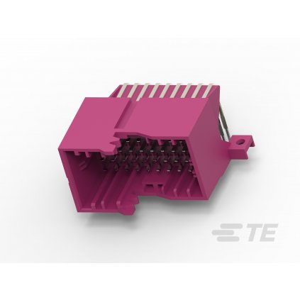
Tělo netěsněného konektoru řady MCP TE Connectivity 36POS,TAB1.5X0.64,HEADER ASSY,CODB,90DEG; počet kontaktů: 36
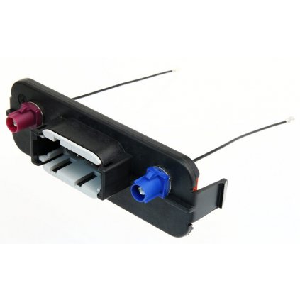
Víčko krabičky EEC 12 pólů; nikl/cín; s 2x FAKRA konektory s kablíky a U.FL(f) konektory

Adaptér konektoru řady DT DEUTSCH Adaptér k DT 04-6P; 90°; w/o; počet kontaktů: 6
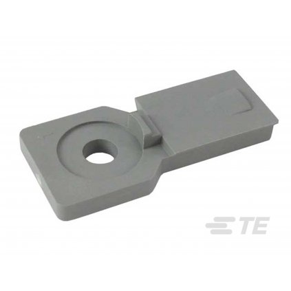
Příslušenství konektorů řady DT DEUTSCH Držák DT 8; plastový; šedý

Tělo těsněného konektoru řady HDSCS TE Connectivity Konektor HDSCS pro dutinku 8x mix (4x 2.8; 2x 6.3/4.8K; 2x blank); skupina E; modrý; počet kontaktů: 6

Tělo těsněného konektoru řady HDSCS TE Connectivity Konektor HDSCS pro dutinku 8x mix (6x 2.8; 2x 6.3/4.8K); skupina E; modrý; počet kontaktů: 8
Jsme největší velkoobchodní distributor DIV TE Connectivity v Evropě
a systémoví integrátoři společností Topcon, Murphy a MRS Electronic.

Naší nabídku na e-shopu neustále rozšiřujeme a doplňujeme aktuální informace a novinky.
Pokud jste i přesto nenašli, co jste hledali, napište si o doplnění položek, které Vás zajímají.
Rádi Vám také poskytneme technickou podporu.
